 is my reworking of the classic 1960’s low pass filter module.")

New
 is my reworking of the classic 1960’s low pass filter module.")
 is my reworking of the classic 1960’s low pass filter module.")
 is my reworking of the classic 1960’s low pass filter module.")
Zoom the image with the mouse
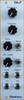
Oakley Modular Euro Discrete Ladder Filter
$49.00 - $249.00
The Oakley Discrete Ladder Filter (DLF) is my reworking of the classic 1960’s low pass filter module. Inspired by the circuits of the 904A filter and CP3 mixer, the DLF combines them into one excellent sounding 6HP wide module.
The audio signal pathway is almost all discrete components with a dual IC op-amp only providing the input and output signal processing for the drive control.
Before entering the 904A style filter core, the audio signal passes through a clone of the CP3 mixer. The original CP3 module had two outputs, an inverted output and a non inverted output. Apart from the change in phase, the two outputs sounded different to one another when the input signal was particularly loud and the output of the CP3 started to clip.The distortion heard when clipping takes place is both unique and musically interesting. The Oakley DLF has a front panel switch to select which of the input stage’s two outputs go on to the filter
circuit, Mode A or Mode B. The DLF’s input stage has been designed to start to clip when the input signal is around +/-4V, but keeping the signal below this will ensure a clean signal.
Turning up the DLF’s Drive control allows the filter core to be overdriven, without changing the output volume, and dramatically changes the sound at higher resonance settings. The Drive control only affects the filter core and has no affect on the input stage. So with variations in input level and drive level it is possible to utilise the overdrive characteristics of only the input stage, only the filter, or both for a really heavy sound.
The filter will self oscillate at high resonance. However, like the original module, the filter won’t self oscillate much below 75Hz. When sweeping the filter’s cut-off frequency at high resonance, this limited resonance at low frequencies gives the filter a powerful bass sound.
Although the module can be used as a filter module on its own, it is expected that you use an external mixer, such as the Oakley Multimix, to combine and control the audio levels going into the module.
Two control voltage (CV) inputs are available on the front panel. CV1 offers the standard 1V/octave control over the cut-off frequency. While CV2 has a depth control which can be varied from off to up to 0.5V/octave, and has additional switch that can invert CV2 if negatively going sweeps are desired.
The module requires +/-12V and has a current consumption of +60mA and -50mA.
The DLF module comprises of two printed circuit boards (PCBs) connected together with four 0.1 (2.54mm) single in line (SIL) headers and sockets. The main board on the rear of the module houses the power input and conditioning, the filter core, and CV processing circuitry. The pot board has the pots, switches, and sockets that are attached to the front panel, as well as the discrete input stage, overdrive circuitry
and CV2 processing circuit. To achieve good circuit performance in a small space both boards are four layer designs. Each board is the same size; 29 mm x 107 mm.
The majority of the components are surface mount parts. The dual op-amps are SOIC, while the resistors and surface mount capacitors are
0805. The dual matched transistors are in small SOT457 packages. There is no requirement to hand match transistors. All components
are standard parts.
Related Products
New
Sold out


New
Sold out
")
")
Sold out


New
Sold out


Customer Reviews
Customers Also Viewed
New
Sold out
New
Sold out
Sold out
New
Sold out