Barton BMC027 Random Rhythms
Barton BMC027 Random Rhythms
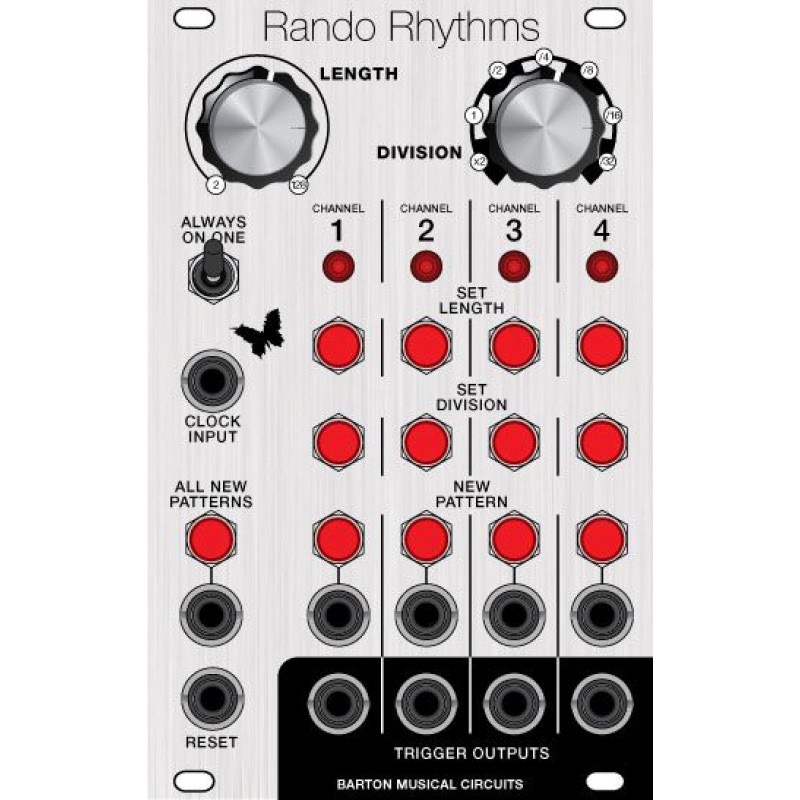
The Random Rhythm module is a 4 channel randomized rhythm sequencer. A single clock controls all four channels. The length and rhythmic subdivision of each channel can be controlled separately. There are additional controls for resetting all sequences to 1 and forcing an onbeat on the first beat of channel 1's sequence.
euro panel by clarke robinson 16hp
kits include everything you need for the module including parts individually bagged and labelled
The Random Rhythms module is a compositional tool for synthesists. It randomly generates
rhythmic patterns and outputs them as triggers. It has four channels of rhythms. All channels are
driven by a single clock input. The length of the rhythmic pattern and the level of rhythmic
subdivision for each channel can be adjusted separately. Length is determined by counting the
number of clock inputs before resetting the sequence, the minimum number is 2 and the maximum
number is 128. The level of rhythmic division is between x2 clock speed to /32.
KNOB BASED CONTROLS
1. Length. This knob sets length of each pattern, it works in conjunction with the "set length" button corresponding to each channel.
2. Division.This knob sets division of each pattern, it works in conjunction with the "set division" button corresponding to each channel.
BUTTON BASED CONTROLS
1-4. Set Length. This button is repeated for each channel. When pressed, the position of the Length knob is read and the corresponding length is assigned to that channel.
5-8. Set Division. This button is repeated for each channel. When pressed, the position of the Division knob is read and the corresponding division is assigned to that channel.
9-12. New Pattern. This button is repeated for each channel. When pressed, a new pattern is randomly generated for that channel.
13. New ALL. This button creates a new pattern on all channels.
INPUTS/OUTPUTS/OTHER
1-4. New Pattern Input. These inputs work in parallel with the New Pattern buttons, when a trigger or gate is inputted, a new pattern is generated for that channel.
5-8. Trigger Outputs. These are the trigger outputs for each channel.
9. Clock Input. This is the input for the clock which drives each of the outputs.
10.Reset Input. Whenever a rising edge of a trigger or gate is detected on this input, it sets it so that all outputs will play the first beat of their sequence on the next clock input.
11.1 ON switch. This is a toggle switch, when activated it sets the 1st beat of output 1 to always be on, instead of being left to chance. The rest of the pattern is still randomly generated.
12. New ALL. This input works in parallel with the New All button.
These kits and assembled modules are offered on demand, click the link to learn more.
| Kit Parameters | |
| Build Difficulty | Moderate |
| Parts Count | 117 |
| SMT parts | 0 |
| Module Parameters | |
| Format | Eurorack |
| Panel Size | 16HP |


