MFOS Noise Cornucopia PCB

MFOS Noise Cornucopia PCB
Content courtesy of Ray Wilson.
Features
|  |
Sample MP3 Files
Introduction
Cornucopia: a symbol of plentitude, strong harvests and abundance. This circuit delivers a plentitude of noise, a veritable harvest of noise, yes, I dare say... an abundance of noise. Noise, noise and more noise. This circuit gives you white noise, pink-ish noise, high pass noise, grainy noise (with grainy adjust), and lastly adjustable random gates. Noise lovers take heart this board was made for you.
Noise Cornucopia Revision 1 Schematic Page 1 PDF
In the Noise Cornucopia, the noise source is the reverse-biased emitter-base junction of Q1. We cut off the collector of Q1 so that it doesn't act like an antenna picking up unwanted noise or EMI. The BVEBO (Emitter-Base Breakdown Voltage) is exceeeded thus the transistor is operating in avalanche mode. More noise info can be found here: Random Electrical Noise: A Literature Survey - by Terry Ritter.
The positive supply voltage is applied to the emitter of Q1 via R33 and R2, 470K resistors in series. Capacitor C18 filters the voltage applied to the emitter to reduce the possibility of supply ripple getting into the noise output. Q1's base is connected to the negative supply via R34, 10K resistor. This configuration results in more symmetry in the noise output. The noise generated at the EB junction of Q1 is capacitively coupled to the non-inverting input of U1-A which is biased to ground by R4 (2M) resistor. A gain of 48 is added by U1 and it's output is fed capacitively to adjustable gain block U1-B. R5 is used to adjust the level of the noise at the output of U1-B to approximately +/-5V P-P.
Adjust R8 for approximately +/-5V peaks in the noise signal.
I found that just about any 2N3904 provided enough noise for this circuit but you may have to try a few to find the noisiest. Try to find the one that needs the least gain out of the second gain block to give you the required +/-5V P-P. The 2N5172 is another good noise transistor choice but note the difference in the pinout if you use it.
U2-A and associated components comprise a high pass filter which gives the noise a very nice hissing quality. U2-B and associated components comprise a low pass filter which gives the noise a very nice Niagra Falls kind of sound. The plain white noise is provided by the output of U1-B.
The plain noise is applied to the inputs of window comparator U3-A/U3-B and associated components, and single sided comparator U4. The window comparator delivers high pulses (approx. -12V to +12V) when the noise exceeds the high window threshold voltage and low pulses (approx. +12V to -12V) when the noise exceeds the low window threshold voltage. The high and low pulses pass thru D1 and D2 respectively and are dropped across resistors R15 and R21 which act as a voltage divider to lower the level of the noise appearing on the Grainy Noise output. At the cathodes of D1 and D2 spikes go from ground to -12 or ground to +12 depending on which side of the window is being exceeded. A passive high pass filter (C15 and R23) is applied to Grainy Noise and not too surprisingly results in the Hi-pass Grainy Noise output.
The Graininess adjust works by setting the size of the window for the window comparator. When wide (low setting), fewer noise peaks exceed the high and low voltage thresholds. As the window is narrowed more and more noise peaks exceed the high and low thresholds and thus more and more high and low pulses occur. This causes the noise to go from a few ticks to a full rainstorm/hailstorm/meteor shower... whatever.
The noise applied to the single sided comparator U4 is slightly filtered by the passive low pass R26, C17, R27 and applied to the non-inverting input of U4. The threshold for comparator U4 is set by the Gate Frequency pot R28. When noise peaks exceed the threshold set by R28 the output of U4 goes high (from approx. -12 to +12V). The positive excursions are fed through D3 and dropped on R29. These pulses provide a clock to the CD4024 7 stage binary counter. Since the clocks do not occur at a regular frequency the counter's outputs change randomly. The most randomness occurs at the low Qs with less randomness at higher Qs. This is because higher counts begin to average the time between pulses so while they will still have a random element they will seem more regular. The board provides jumpers for you to choose which CD4024 output you want to use. You can temprarily jump the outputs to the junction of R30/R32 to see which output suits your random gate tastes or just choose the one I did (Q5) and insert the jumper in the space indicated by the parts legend. Q2 drives the Gate indicator LED to indicate the presence of gate high.
If you notice that the random gates are not being output it may be that you need to reduce the value of C17 .0047 uF ceramic capacitor to .0022uF or .001uF. C17 filters out a lot of the high frequency of the noise which includes many of the large transients. If the level of the noise applied to the non-inverting input of U4 is not high enough to get over the threshold level set by R25, R38 and R21 you can also reduce the value of R31 to 18K or 15K which will reduce the level of noise necessary to exceed the threshold (lowered by lowering the value of R31).
| Approx. Current Consumption | |
| +12V | 15mA |
| -12V | 13mA |
Assume slightly more current at +/-15V.
Noise Cornucopia Revision 1 PCB Parts Layout (Parts Side Shown) PDF
| You can use a 2N3904 or a 2N5172 for the noise transistor. Select the noisiest one you can find in your parts drawer. | If using the 2N3904 the transistor is inserted normally as shown here. This is because the 2N3904 pinout viewed from front is E-B-C. Cut off the collector regardless of which you use. | If using the 2N5172 you need to mount the transistor as shown. This is because the 2N5712 pinout viewed from front is E-C-B. Cut off the collector regardless of which you use. |
 |  |  |
Noise Cornucopia Revision 1 PCB Part Values Layout (Parts Side Shown) PDF
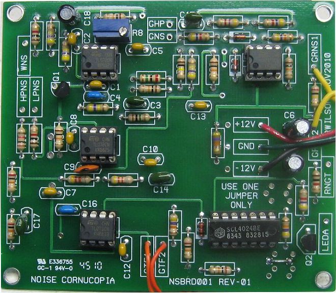
Noise Cornucopia Revision 1 Populated PC Board Larger Image
Noise Cornucopia Revision 1 PCB Bottom Copper (Parts Side Shown)
Noise Cornucopia Revision 1 PCB Top Copper(Parts Side Shown)
Noise Cornucopia Revision 1 PCB Top Silk Screen
Noise Cornucopia Revision 1 Front Panel and Wiring PDF 
Noise Cornucopia Revision 1 Project Parts List
- Using 1% metal film resistors everywhere will reduce temperature related drift.
- Where 1% metal film is specified 5% carbon comp will work but with more temperature drift.
- Usually biFET amps (quads, duals, singles) can be replaced with an equivalent from another manufacturer.
- Capacitors can be film, ceramic, or silver mica.
- LM13700 subs (if applicable) (LM13600, NE5517, AU5517, NTE870).
| Qty. | Description | Value | Designators |
|---|---|---|---|
| 1 | CD4024 7 Stage Binary Counter | CD4024 | U5 |
| 1 | TL071 Op Amp | TL071 | U4 |
| 3 | TL072 Dual Op Amp | TL072 | U1, U2, U3 |
| 2 | 2N3904 | 2N3904 | Q1, Q2 |
| 3 | 1N914 High Speed Diode | 1N914 | D1, D2, D3 |
| 1 | General Purpose LED | LED | LED1 |
| 2 | Linear Taper Potentiometer | 100K | R18, R28 |
| 1 | Resistor 1/4 Watt 5% | 100K | R6 |
| 5 | Resistor 1/4 Watt 5% | 10K | R5, R9, R14, R20, R34 |
| 4 | Resistor 1/4 Watt 5% | 1K | R1, R3, R11, R32 |
| 1 | Resistor 1/4 Watt 5% | 1M | R7 |
| 1 | Resistor 1/4 Watt 5% | 200K | R19 |
| 4 | Resistor 1/4 Watt 5% | 20K | R26, R27, R29, R31 |
| 1 | Resistor 1/4 Watt 5% | 2M | R4 |
| 4 | Resistor 1/4 Watt 5% | 4.7K | R15, R21, R23, R24 |
| 2 | Resistor 1/4 Watt 5% | 43K | R16, R17 |
| 4 | Resistor 1/4 Watt 5% | 470K | R2, R10, R12, R33 |
| 4 | Resistor 1/4 Watt 5% | 47K | R13, R22, R25, R30 |
| 1 | Trim Pot | 500K | R8 |
| 2 | Ceramic Capacitor | .001uF | C3, C15 |
| 1 | Ceramic Capacitor | .0047uF or .005uF | C17 |
| 1 | Ceramic Capacitor | .01uF | C14 |
| 8 | Ceramic Capacitor | .1uF | C1, C2, C5, C7, C8, C10, C12, C13 |
| 1 | Ceramic Capacitor | 100pF | C9 |
| 2 | Ceramic Capacitor | 10pF | C4, C16 |
| 2 | Electrolytic Capacitor | 10uF | C6, C11 |
| 1 | Electrolytic Capacitor | 1uF | C18 |
Miscellaneous
- 1/16" Thick aluminum plate for mounting the pots and switches.
- Unit is typically mounted in a synth case with other synth modules.
- Assorted hardware 1" 6-32 nuts and bolts, 1/2" #8 wood screws, etc
- Knobs for potentiometers, wire and solder.
- Digital Volt Meter and a Signal Tracer or oscilloscope for testing.