MFOS Stereo Panning Mixer PCB
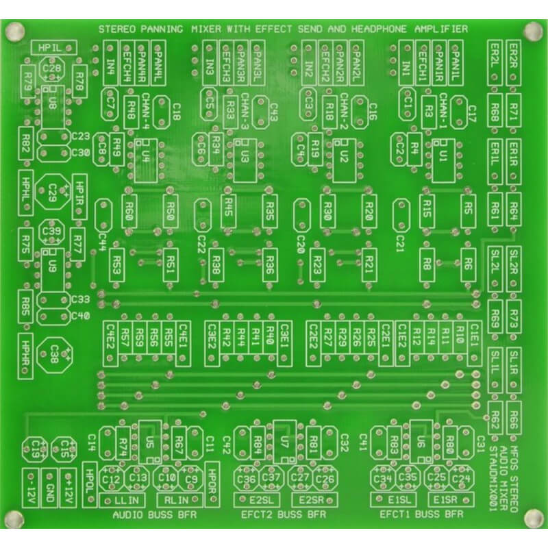
MFOS Stereo Panning Mixer Synth Module Bare PCB
(stereo audio mixer label on PCB)
content courtesy of Ray Wilson:
Features
|  |
Introduction
Who in their right mind would build a mixer when you can buy a nice small Behringer Mixer for about 40 bucks? I don't know... probably me..., and maybe some other steely-eyed, hard-core, solder junkie, synth-diy'er that's who :-)
A versatile stereo mixer for use with your synth modules. You can easily change gains on the mono input channels to accomodate high-Z microphones (not balanced input mics), electric guitars or other instruments. By adding another board and populating only the mono inputs (or mono inputs and stereo input components) you can add more channels to the audio and effect busses of the first fully populated board. More details on this configuration can be found below.
Stereo Mixer Schematic Page 1 PDF
In the Stereo Mixer there are four mono input channels and four sets of stereo line inputs. Each mono input consists of a level pot, capacitively coupled to a buffer amplifier. Channel one for example has R2 (100K audio taper pot) as the input level control. The wiper is connected via C1 and R3 to U1 (TL071 low noise op amp) which provides a gain of 10. Changing Channel Gains Feedback resistors in any of the mono input channels can be independently adjusted to provide more or less gain for any channel. The formula for gain is very simple (feedback resistor value) divided by (input resistor value) or RFB/RIN. Each channel is shown with 47K input resistor and a 470K feedback resistor (giving a gain of 10 (470,000/47,000)). To decrease the input channel gain to 1.0 (for high level synth signals) use 470K resistors for the buffer input resistors (R3, R18, R33, R48). To increase the input channel gain to about 21 change the feedback resistors in the input buffers to 1M (R4, R19, R34, R49). Use the formula above to tailor the gain to your needs. The small capacitor across the feedback resistor is there to prevent oscillation since the op-amps are not set for a gain of one. The channel 1 buffer feeds its panning circuit R5,R6,R7,R15,R8 which is used to send the signal to the right and left audio buss. The pan pot R7 brings the junction of R5,R6 or R15,R8 closer to or further from ground which causes the signal through either path to be attenuated when the wiper connected to ground is brought close to either one. This causes the signals being fed to the right and left audio buss to appear to be biased either left or right in the stereo field. The channel buffer output also feeds the effect send pots for the channel. Each effect send pot has two resistors connected to its wiper that are fed to the effect buffer busses. The effect buffers for Effect Send 1 are U6-A and U6-B (Tl072 dual low noise op amp). The effect buffers for Effect Send 2 are U7-A and U7-B (Tl072 dual low noise op amp). The audio buss buffers are U5-A and U5-B (Tl072 dual low noise op amp). The output of the audio buss buffers are used to feed headphone level pot R76 (dual audio taper 100K pot) whose wiper feed the headphone amps (U8 and U9 LM386 low voltage audio power amplifiers) via attenuators (R75 & R77 and R78 & R79). The effect returns and stereo line inputs are fed to the audio buss via the pots used as attenuators for each of the input pairs and the summing resistors. This is a very simple design and gains can be changed anywhere in the circuit by changing the values of individual summing resistors or feedback resistors in any of the op amp circuits. If you want more input channels you can build another board but do not add the audio buss buffers, effect send buffers, or headphone amplifiers. Connect the second boards busses to the completely assembled board and it will provide the buffers for all channels. See part layouts highlighting what I mean below. It goes without saying (but obviously I'm saying it) that the second board will also need to be connected to the power supply. |
Stereo Mixer Schematic Page 2 PDF
Setting Gains
A builder pointed out that the gain of "Stereo Line Input 1" is higher than the gain of "Stereo Line Input 2" due to the lower vlues of the input resistors. Stereo Line Input 1 uses 150K for R62 and R66 whereas Stereo Line Input 2 uses 47K for R69 and R73. As shown "Stereo Line Input 2" will be hotter (have higher gain) than "Stereo Line Input 1". To make these inputs operate at the same gain change R62 and R66 to 47K (both stereo inputs will have the higher gain) or change R69 and R73 to 150K, (both stereo inputs will have the lower gain). Throughout the circuit gains can be changed as desired by manipulating feedback or input resistors. For the feedback resistor, gain goes up if it is made larger in value and gain goes down if it is made smaller in value. The opposite is true for the input resistors.
Stereo Mixer Expanding For More Input Channels
To expand to eight mono input channels you use another board and only populate the mono input sections. You can populate the stereo line input components too if you want more stereo line inputs. Both boards must be powered from the supply and ground. Run jumpers from the partially populated (expander) board to the fully populated board to bring the mono channels to the stereo buss, effect busses and headphone amplifiers. Of course you need another set of pots and jacks for the four mono input channels. They should be wired in the same manner as the original four channels. I don't know a better way to explain this but if I have not described using another board for expansion clearly enough please consult one of your electronically oriented friends to see if they can help. Good luck.
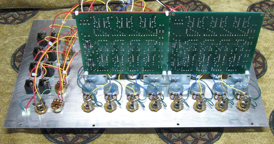
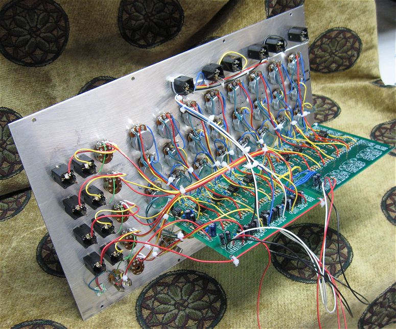
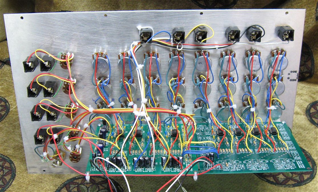
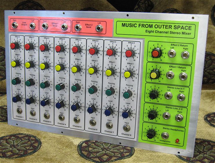
Some Pics Of My Expanded Eight Channel Mixer
You can see how the one board is fully populated with components but the second board only has the components to support the additional input channels.
 |  |  |  |
| Approx. Current Consumption | |
| +12V | 31 mA |
| -12V | 19 mA |
| +15V | 33 mA |
| -15V | 19 mA |
Stereo Mixer PCB Parts Layout (Parts Side Shown) PDF
Stereo Mixer PCB Part Values Layout (Parts Side Shown) PDF
Stereo Mixer PCB Bottom Copper (Parts Side Shown)
Stereo Mixer PCB Top Copper(Parts Side Shown)
Stereo Mixer PCB Top Silk Screen
Panel Drawings Updated
I updated this panel drawing so that it is 10.5 inches wide and 8.75 inches tall. This panel will take up 3 bays of a synth panel designed for 2 rows of 5 modules using 3.5" x 8.75" inch modular panels. Here are links to the old documents for reference.Stereo Mixer Front Panel and Wiring PDF
This wiring layout and front panel are only suggestions. The wiring drawing is meant to show how the front panel is connected to the wiring points on the PC board. Whether you use coax cable is up to you for the panel to board wiring. Don't write to me about this. You can also shield the unit by building it into an aluminum box.
Stereo Mixer Front Panel Overlay PDF
Stereo Mixer Project Parts List
- Lower noise higher performance (higher cost) Op-Amps are always welcome.
- Usually biFET amps (quads, duals, singles) can be replaced with an equivalent from another manufacturer.
- Capacitors can be film, ceramic, or silver mica.
Stereo Mixer Project Parts List
| Qty. | Description | Value | Designators |
|---|---|---|---|
| 4 | TL071 Op Amp(s) | TL071 | U1, U2, U3, U4 |
| 3 | TL072 Dual Op Amp(s) | TL072 | U5, U6, U7 |
| 2 | LM386N-4 Low Voltage Audio Power Amp(s) | LM386N-4 | U8, U9 |
| 1 | LED | LED | LED1 |
| 2 | Capacitor Electrolytic(s) | 10uF | C19, C15 |
| 2 | Capacitor Electrolytic(s) | 1uF | C28, C39 |
| 2 | Capacitor Electrolytic(s) | 220uF | C29, C38 |
| 12 | Capacitor Electrolytic(s) | 47uF | C9, C12, C37, C24, C36, C27, C26, C34, C35, C25, C10, C13 |
| 2 | Ceramic Capacitor(s) | .047uF | C40, C30 |
| 14 | Ceramic Capacitor(s) | .1uF | C1, C3, C5, C7, C16, C20, C17, C21, C18, C22, C23, C33, C44, C43 |
| 10 | Ceramic Capacitor(s) | 10pF | C2, C4, C6, C8, C32, C42, C41, C31, C14, C11 |
| 5 | Dual Gang Pot(s) Audio Taper | 100K | R63, R70, R65, R72, R76 |
| 12 | Potentiometer(s) Audio Taper | 100K | R2, R9, R13, R17, R24, R28, R32, R39, R43, R47, R54, R58 |
| 4 | Potentiometer(s) Linear Taper | 100K | R7, R22, R37, R52 |
| 21 | Knobs | For all pots | |
| 2 | Resistor 1/4 Watt 5%(s) | 10 ohm | R82, R85 |
| 2 | Resistor 1/4 Watt 5%(s) | 100K | R77, R78 |
| 16 | Resistor 1/4 Watt 5%(s) | 120K | R5, R6, R15, R8, R20, R21, R30, R23, R35, R36, R45, R38, R50, R51, R60, R53 |
| 6 | Resistor 1/4 Watt 5%(s) | 150K | R61, R68, R64, R71, R66, R62 |
| 4 | Resistor 1/4 Watt 5%(s) | 15K | R80, R83, R81, R84 |
| 16 | Resistor 1/4 Watt 5%(s) | 20K | R10, R12, R11, R14, R25, R27, R26, R29, R40, R42, R41, R44, R55, R57, R56, R59 |
| 2 | Resistor 1/4 Watt 5%(s) | 300K | R67, R74 |
| 3 | Resistor 1/4 Watt 5%(s) | 4.7K | R79, R75, R86 |
| 4 | Resistor 1/4 Watt 5%(s) | 470K | R4, R19, R34, R49 |
| 6 | Resistor 1/4 Watt 5%(s) | 47K | R3, R18, R33, R48, R69, R73 |
| 1 | Stereo Headphone Jack | Stereo Jack | J17 |
| 18 | 1/4" Phone Jack(s) | Phone Jack | J2, J3, J4, J1, J7, J14, J15, J18, J16, J19, J5, J8, J10, J12, J6, J9, J11, J13 |
Miscellaneous
- 1/16" Thick aluminum plate for mounting the pots and switches.
- Unit is typically mounted in a synth case with other synth modules.
- Assorted hardware 1" 6-32 nuts and bolts, 1/2" #8 wood screws, etc
- Lots of Knobs for potentiometers, wire and solder.
- Digital Volt Meter and a Signal Tracer or oscilloscope for testing.