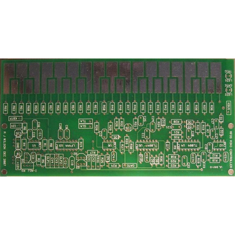
MFOS Minicontroller PCB
MFOS Minicontroller
product page here: minicontroller
content courtesy of Ray Wilson
The value of R7 has been changed from 1M to 10M. Doing so reduces the current through R7 and subsequently increases the precision of the bus voltage when a key is pressed. A voltage divider exists between the resistor ladder and R7. By increasing the value of R7 by a factor of 10 the output of the resistor ladder is loaded less (by 10X) when a key is pressed.
Features
Quirks
MFOS Mini-Controller MP3 SamplesShort song using the Mini-Controller. | 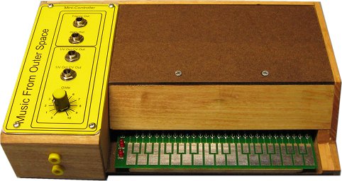 |
Introduction
If you are into the synth hobby scene this is a "must have" you will be playing with this thing into the wee hours of the morning especially if you built a Sound Lab and don't already have a keyboard controller or you are planning on building a Sound Lab. This thing has added a new dimension to the fun I have with my Sound Lab. My son built one for his Sound Lab and he says he can't put it down.
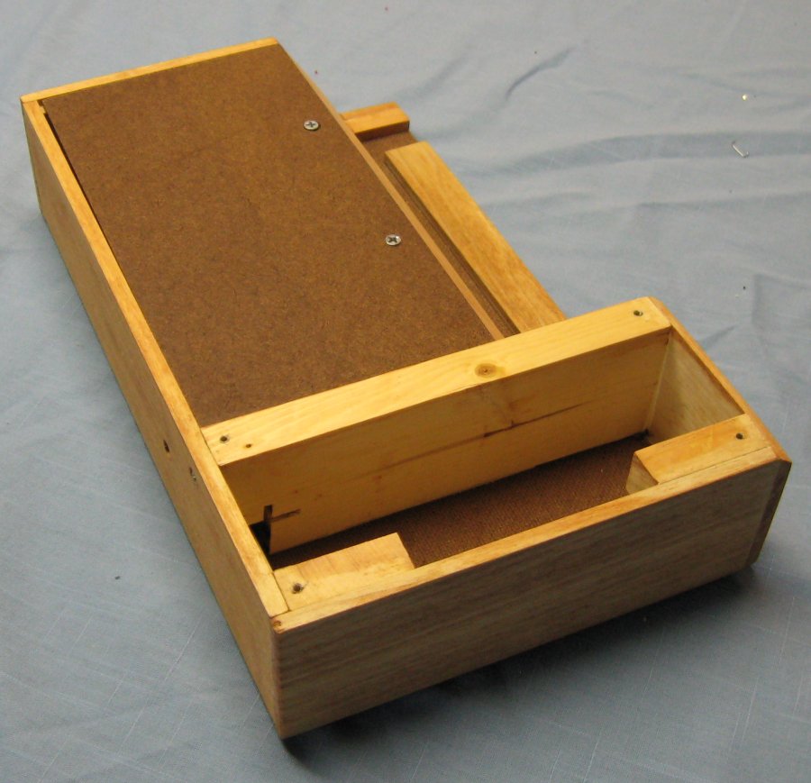
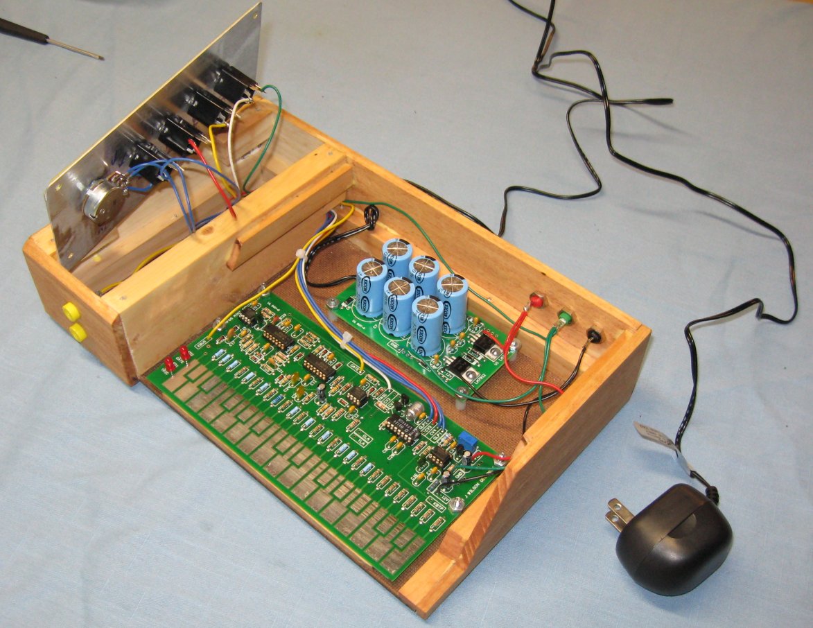
More Photos
 |  |  |  |
 |  |  |  |
MFOS Mini-Controller Schematic Page 1 PDF
This circuit is identical to the one in the Single Buss 1V/Octave Keyboard Controller. See the circuit description there. This board has the addition of the resistors used in the keyboard voltage divider. Whereas in typical keyboard pressing a key brings the resistor divider in contact with the main buss we bring the bus to the divider via the probe used to touch the PCB pads that represent the keyboard.
MFOS Mini-Controller Schematic Page 2 PDF
This is the full resistor divider that is used to produce the 1V per octave voltage necessary to control the Sound Lab or other moddular synthesizer.
| Approx. Current Consumption | |
| +12V | 30mA |
| -12V | 30mA |
| +15V | 32mA |
| -15V | 32mA |
MFOS Mini-Controller PCB Parts Layout Legend View (Parts Side Shown) PDF
MFOS Mini-Controller PCB Parts Layout Value View (Parts Side Shown) PDF
MFOS Mini-Controller PCB Bottom Copper (Parts Side Shown)
MFOS Mini-Controller PCB Top Copper(Parts Side Shown)
MFOS Mini-Controller PCB Top Silk Screen
MFOS Mini-Controller Front Panel and Wiring PDF
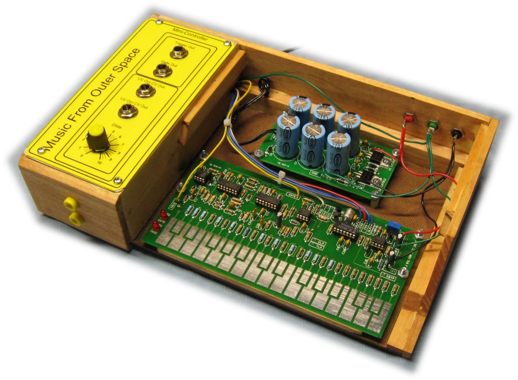
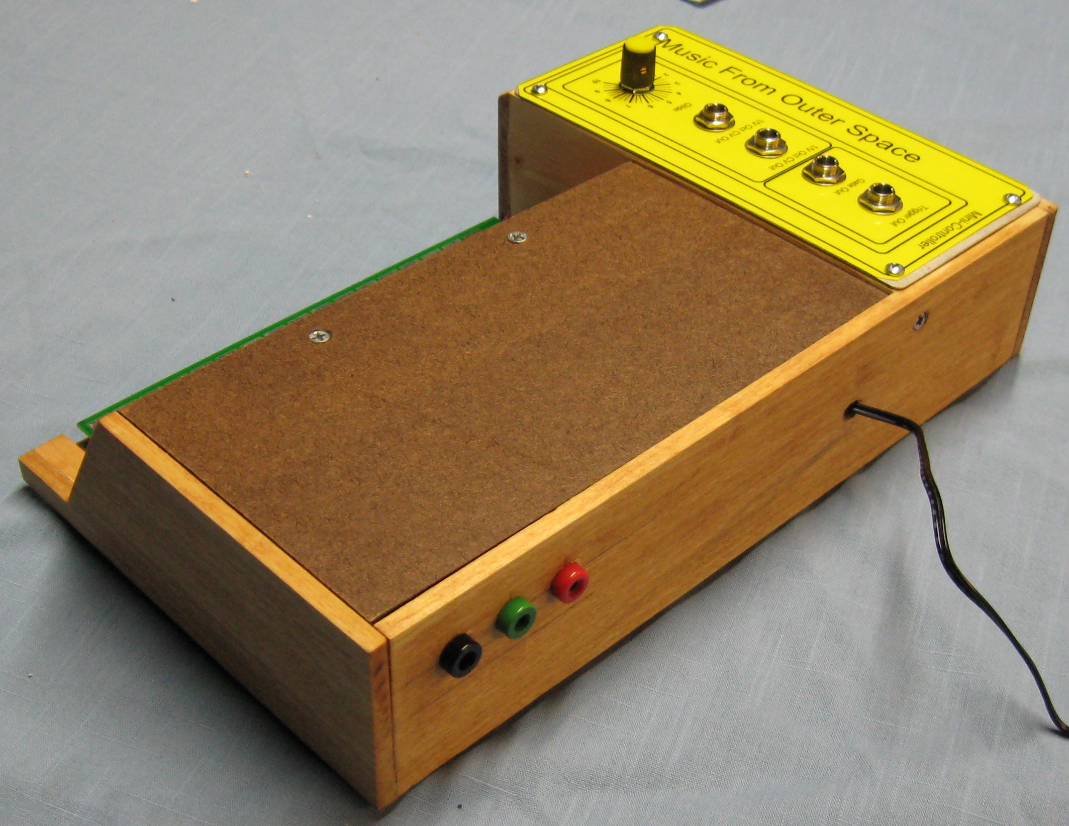
As you can see in the photos above I combined the MFOS Wall Wart Power Supply with the MFOS Mini-Controller and also fed the +12V, -12V and Ground out via banana jacks so I can power my Sound Lab Mini-Synth. It is very convenient. You only connect the PCB points shown here and of course KBUS to the banana jacks so you can connect the wand to them. There are several PCB connection points that are not used unless you score a real keyboard and then use this board to build a regular keyboard. Then you might want to use TLA (Trigger LED Anode), GLA (Gate LED Anode), and KBTP (keyboard top) as described in this article Single Buss 1V/Octave Keyboard Controller. As far as the Mini-Controller circuit is concerned when you plan to use the touch pads everything is already pre-connected on the PC board and you just leave these as they are.
KBUS Is Where The Wand Gets Connected | ||
| ||
Old Meter Probe Makes A Good WandI have several old meter probes lying around and they make a great wand. I suggest that you dull the tip. | ||
 | ||
Not All Board Connection Points Are Used | ||
| You only connect the PCB points shown here. There are several PCB connection points that are not used unless you score a real keyboard and then use this board to build a regular keyboard. Then you might want to use TLA (Trigger LED Anode), GLA (Gate LED Anode), and KBTP (keyboard top) as described in this article Single Buss 1V/Octave Keyboard Controller. As far as the Mini-Controller circuit is concerned when you use the key-pads everything is already pre-connected on the PC board and you do not need to connect the PCB connection points you see here with no wires going to them. Additionally if you use this PCB for a keyboard you would remove the LEDs, and the keyboard voltage ladder resistors.
|


MFOS Mini-Controller Project Parts List
- Using 1% metal film resistors everywhere will reduce temperature related drift.
- Where 1% metal film is specified 5% carbon comp will work but with more temperature drift.
- Usually biFET amps (quads, duals, singles) can be replaced with an equivalent from another manufacturer (except for the LF444).
- Capacitors can be film, ceramic, or silver mica.
MFOS Mini Controller Parts List
| Qty. | Description | Value | Designators |
|---|---|---|---|
| 1 | TL071 Op Amp | TL071 | U1 |
| 2 | TL082 Dual Op Amp(s) | TL082 | U2, U6 |
| 2 | TL084 Quad Op Amp(s) | TL084 | U5, U4 |
| 1 | LF444 Quad Op Amp (do not sub) | LF444 | U3 |
| 11 | 1N914 Sw. Diode(s) | VALUE | D5, D4, D1, D2, D3, D6, D10, D7, D11, D8, D9 |
| 1 | 2N3906 | 2N3906 | Q1 |
| 2 | 2N5457 N(s) | 2N5457 | Q2, Q3 |
| 2 | LED(s) | LED | LED1, LED2 |
| 1 | Capacitor Ceramic | .001uF | C18 |
| 2 | Capacitor Ceramic(s) | .0047uF | C25, C24 |
| 1 | Capacitor Ceramic | .01uF | C1 |
| 15 | Capacitor Ceramic(s) | .1uF | C6, C7, C9, C11, C10, C12, C13, C14, C20, C2, C3, C4, C5, C16, C22 |
| 1 | Capacitor Ceramic | 22pF | C23 |
| 2 | Capacitor Ceramic(s) | 470pF | C21, C17 |
| 1 | Polystyrene or Polycarbonate (low leackage) Capacitor | .01uF | C19 |
| 3 | Electrolytic Capacitor (S)(s) | 10uF | C8, C15, C26 |
| 1 | Potentiometer | 1M | R11 |
| 28 | Resistor 1/4 Watt 1%(s) | 100 ohm | R37, R38, R39, R40, R41, R42, R43, R44, R45, R46, R47, R48, R49, R50, R51, R52, R53, R54, R55, R56, R57, R58, R59, R36, R60, R61, R62, R63 |
| 4 | Resistor 1/4 Watt 5%(s) | 100K | R23, R9, R32, R33 |
| 3 | Resistor 1/4 Watt 5%(s) | 10K | R15, R13, R21 |
| 1 | Resistor 1/4 Watt 5% | 150K | R22 |
| 2 | Resistor 1/4 Watt 5%(s) | 1K | R27, R25 |
| 6 | Resistor 1/4 Watt 5%(s) | 1M | R1, R19, R20, R10, R30 |
| 1 | Resistor 1/4 Watt 5% | 20 Ohm | R8 |
| 1 | Resistor 1/4 Watt 5% | 200K | R34 |
| 3 | Resistor 1/4 Watt 5%(s) | 20K | R24, R26, R16 |
| 1 | Resistor 1/4 Watt 5% | 3.9K | R2 |
| 1 | Resistor 1/4 Watt 5% | 300K | R31 |
| 1 | Resistor 1/4 Watt 5% | 30K | R12 |
| 1 | Resistor 1/4 Watt 5% | 39K | R4 |
| 2 | Resistor 1/4 Watt 5%(s) | 3K | R28, R29 |
| 1 | Resistor 1/4 Watt 5%(s) | 10M | R7 (changed from 1M to 10M Apr 2009) |
| 1 | Resistor 1/4 Watt 5% | 4.7K | R18 |
| 1 | Resistor 1/4 Watt 5% | 475 Ohm | R5 |
| 1 | Resistor 1/4 Watt 5% | 47K | R35 |
| 1 | Resistor 1/4 Watt 5% | 82K | R6 |
| 1 | Resistor 1/4 Watt 5% | 200K | R14 |
| 1 | Resistor 1/4 Watt 5% | 39K | R17 |
| 1 | Multi-turn Trim Pot | 1K | R3 |
Miscellaneous
- 1/16" Thick aluminum plate for mounting the pots and switches.
- Unit is typically mounted in a synth case with other synth modules.
- Assorted hardware 1" 6-32 nuts and bolts, 1/2" #8 wood screws, etc
- Knobs for potentiometers, wire and solder.
- Digital Volt Meter and a Signal Tracer or oscilloscope for testing.


LF444CN Quad Lo Pwr JFET Op-Amp
LF444CN quad lo pwr jfet op amptube contains 25 ICsDIP-14 case ..
$1.58 Ex Tax: $1.58