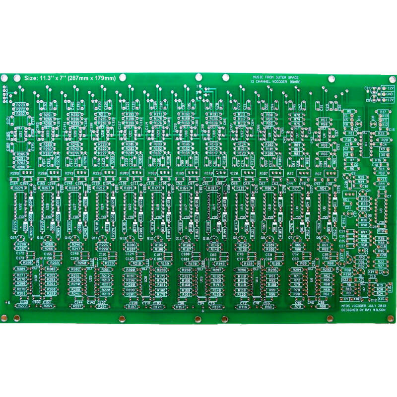
MFOS 12 Channel Vocoder
MFOS 12 Channel Vocoder
More info: MFOS 12 Channel Vocoder
Component kit includes all the pcb parts, panel parts, wire etc you need to build the PCB, but no panel, no case and no power supply. You can order the MFOS WallWart Power supply kit 'add-on' which is 100% compatible.
Content courtesy of Ray Wilson
Features
IntroductionA vocoder has got to be one of the coolest signal processors going. It allows you to impress vocal harmonic and dynamic characteristics onto other sound sources making them sound as if they are talking. This vocoder design works by using one lo-pass filter (100 Hz.), ten successively tuned band-pass filters (154, 208, 285, 395, 542, 720, 1013, 1495, 2000, 2546 Hz.) and one hi-pass filter (3330 Hz.) to separate the incoming control signal into its harmonic constituents. For each band the control signal appearing at the output of its corresponding filter is full wave rectified and low pass filtered to obtain the control signal's envelope voltage. This signal is used to drive a VCA through which the channel's filtered audio is amplitude controlled. The whole circuit is described below but all I can say is that this thing is totally cool and I'm very happy with mine (I am somewhat biased). | 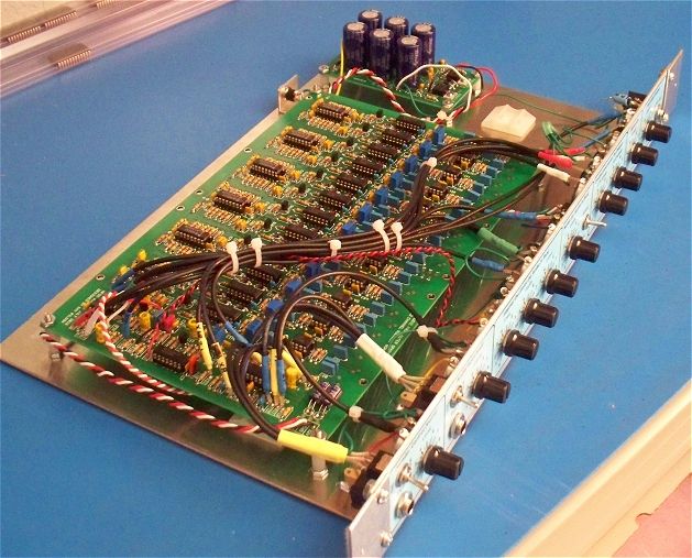 |
User Modifications
I have a good feeling about this project. It's my hope that it becomes one of those that people enjoy building and it's perfect for people who enjoy modifying designs (see Vocoder Expansion and the Filter Design tab). If and when I ever modify mine (who knows, winter's coming...) I'll document it completely in a new sub-tab entitled "Modifications". Any experimenters willing to share schematics/photos of discovered improvements or modifications are invited to let me know at info@musicfromouter...(you know the rest).com. Please include links to sound samples when you email so I can publish them along with the modification information. People will appreciate hearing what the mod results in. As a standard for at least one of the samples (and I suggest you provide several sample links) I propose using one of the sample vocal loops below so everyone knows what the voice control source material sounds like. I'll add the info (or links to it if you prefer) and sound sample links to the "Modifications" page with credit to you for having contributed the idea. Open source comes to vocoders!
Sample MP3s
I really hope you take the time to listen to the samples before embarking on this project. It is a fairly large investment in time and money and I want you to be happy with the results. I am looking forward to using mine in some of my upcoming musical projects and I really like it. The samples will give you a good idea of the speech intelligibility you can expect when used with a decent microphone and a keyboard. Your build will sound similar.
You should also know that a twelve channel vocoder is not going to sound like a DSP plugin or footpedal vocoder. So... before you get out your solder iron expecting one thing... listen to the samples. I love this vocoder and I think it's totally cool but it's kind of like my child by now so you can understand why. If you do build the project I have to say that the board soldered up very nicely and the vocoder worked prefectly after I tracked down one unsoldered resistor lead and calibrated the channel gains. Good soldering.
babadaboopbadubadooda-Track 7.mp3
internaloscillator-Track 1.mp3
pianostringswhitenoise-Track 5.mp3
trumpetandboneswhitenoise-Track 5.mp3
Table of Contents
Calibration - Setting Filter Band Gains
Introduction - Continued
This vocoder design works by using one lo-pass filter (100 Hz.), ten successively tuned band-pass filters (154, 208, 285, 395, 542, 720, 1013, 1495, 2000, 2546 Hz.) and one hi-pass filter (3330 Hz.) to separate the incoming control signal into its harmonic constituents. For each band the control signal appearing at the output of its corresponding filter is full wave rectified and low pass filtered to obtain the control signal's envelope voltage.
Meanwhile the audio (signal to be modified) path is also going through a separate but identical set of twelve filters. The output of each of these filters goes through a VCA that is controlled by the envelope follower output of the corresponding filtered control signal's envelope voltage. Thus when there is harmonic content contained in a band of the control signal a proportional amount of the same harmonic content of the audio signal is passed through it's filter and VCA to the output of the vocoder.
The Vocoder Band Block Diagram shows that each band consists of two identical active filters, an envelope follower and a VCA. The control signal's active filter output feeds an envelope follower whose output voltage controls the VCA. The VCA controls the amplitude of the channel's audio filter output. Thus whenever the control signal contains harmonic content within the pass-band of it's particular filter it turns the VCA on causing the audio signal filtered with the same filter characteristics to be output to the mix bus.
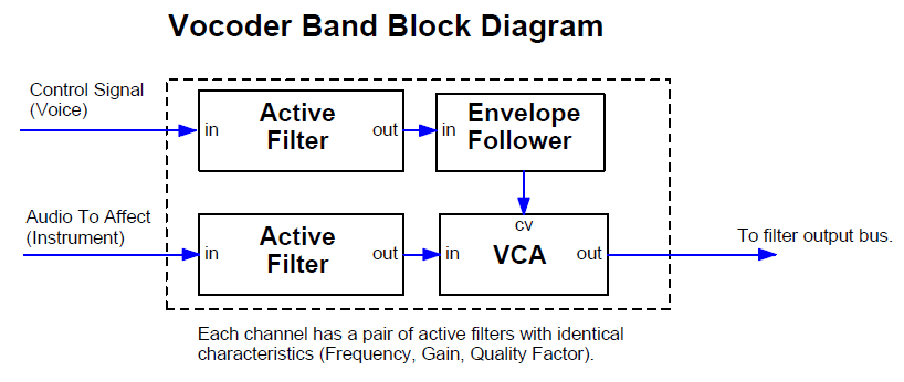
The MFOS 12 Channel Vocoder Block Diagram shows how 12 of these channels, each tuned to a separate band of frequencies are routed to the main output bus. You may have heard one of those guitar effects in which a speaker drives sound into a plastic tube that the musician places in his/her mouth. In that case the musician uses his/her mouth to apply the same physical filtering to the guitar sound coming through the tube as is normally applied to the sound emanating from the musician's vocal cords. The result is that the musician can make the guitar 'talk'.
In a way the vocoder applies similar filtering to the audio signal but uses a more round about way to get there. The audio signal is routed through the lo-pass filter, ten bandpass filters and the hi-pass filter which are controlled by the VCAs. The audio signal path's VCAs and filters are the analog of the mouth's ability to apply acoustic filtering. The amount of each filter's output is directly proportional to the harmonic content contained in the control signal (voice).
The internal oscillator and noise source provide ready-to-go audio signals to experiment with. The white noise, with level adjustment, is also applied to the hi-pass filter's VCA input so that when high frequencies are present white noise is emitted. I did not employ the 'sibilance detect' circuit found in some designs that compare the energy in the lower bands to the energy in the upper bands to see if white noise should be emitted I just let it fly when frequencies above 3330 Hz. are detected. I call my method the poor man's sibilance detector and it seems to work just fine.
You can mix the raw control or audio signals into the output via the Control Mix-In and Audio Mix-In controls. You can select white or pink noise as well as the internal rectangle wave oscillator to be applied to the vocoder input. Using noise as the audio signal creates odd whisper effects and applying the internal oscillator makes you sound like a robot. The output level control adjusts the amount of the unit's signal that is fed to your amp or mixing board.
Use a good quality mic for best results
In the just so you know category: using a quality microphone with a flat frequency response between about 70 to 10,000 Hz. (or better) will result in the best speech intelligibility. Using a low quality mic will be a very disappointing experience. I use my Octava capsule mic into my mix board and then take the output of the channel via the insert jack. Just insert the tip (send) jack's output to the vocoder's Control (voice) input. On most mixers when the stereo-tipped insert plug is in a channel's insert jack the mic is effectively cut off from the rest of the mixer (unless you plug through an effect of some kind). The insert jack is switched such that it expects me to "insert" something and since the insert cable plug to route the signal back onto the mixer's bus is not connected the channel's pre-amp is not connected to the mixer's audio bus.
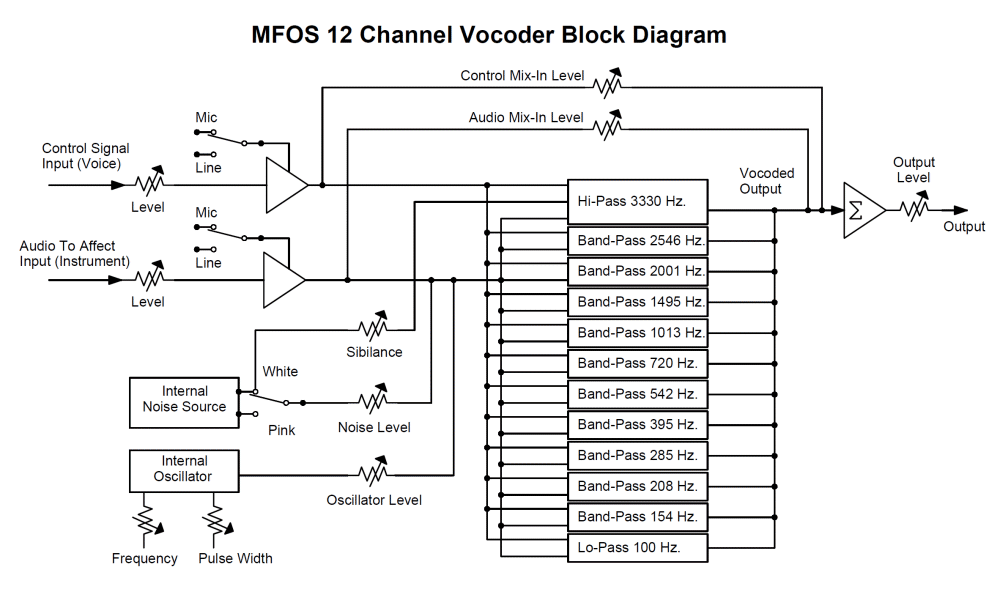
Table 1 presents the characteristics of the filters used in the MFOS vocoder's bands.
Table 1 - Frequency Characteristics of MFOS Vocoder Filters
| Frequency | Type *MFB = Multiple Feedback | Gain | Q |
| 3330 | MFB* Hi-Pass | -2.13 | .88 |
| 2546 | MFB* Band-Pass | -2.8 | 4.48 |
| 2001 | MFB* Band-Pass | -3.15 | 5.16 |
| 1495 | MFB* Band-Pass | -3.4 | 3.2 |
| 1013 | MFB* Band-Pass | -2.8 | 3.9 |
| 720 | MFB* Band-Pass | -2.8 | 3.7 |
| 542 | MFB* Band-Pass | -3.12 | 3.75 |
| 395 | MFB* Band-Pass | -2.5 | 3.7 |
| 285 | MFB* Band-Pass | -3 | 3.55 |
| 208 | MFB* Band-Pass | -2.4 | 4 |
| 154 | MFB* Band-Pass | -2.4 | 2.96 |
| 101 | MFB* Lo-Pass | -2.55 | .55 |
With A Little Help From My Friends...
I looked all over the web to find vocoder designs to learn from. I did not copy anyone's design but got some great ideas and basic principles from these sources. I invite you check them out and learn more about vocoders.
- PAIA Vocoder - Craig Anderton
- Vocal Harmonizer and Vocoder - Philip Decamp, Uriel Klieger, Andrew McPherson
- Okita Vocoder Documentation - N. Okita
- ETI Vocoder Documentation - Richard Becker
Designing filters is hard unless you find cool tools on the web that are freely available. Here are some I found that helped me to succeed with this project.
MFOS Vocoder Schematics
Vocoder Full Schematic
Vocoder Schematic Page 1
Page one of the schematic encompasses a number of the housekeeping functions of the vocoder. U1 (TL074CN) is used to buffer both the control signal (voice) and the audio signal (instrument). Both inputs work in a similar manner so I will only describe the Vocoder Control Input. The Vocoder Control Input jack's tip is connected to Input Level Adjust pot R1 (100K linear taper). The signal picked off of R1's wiper is applied to the non-inverting input of buffer U1-A via C1 (1uF non-polar cap). U1-A applies a gain of 48 (thanks to feedback resistor R11, 47K and R10, 1K to ground) to the adjusted input signal. The 47pF cap across U1-A's feedback resistor mitigates any penchant the op amp may have to oscillate due to its high gain. Switch S1 selects between the output of U1-A or the unamplified signal dropped on R5 (470K resistor). Switch S1's center pole applies the input signal (with or without gain) to the non-inverting input of buffer U1-B (TL074CN). Again C6 (47pF cap) keeps U1-B quiet oscillation-wise. U1-B applies a gain of 5.7 to the signal appearing at it's non-inverting input. Together U1-A and U1-B can apply a maximum gain of 273 to a signal applied to the Vocoder Control Input provided that switch S1 is in Mic position. The output of buffer U1-B feeds both the CTL bus, which applies the control signal to the control signal path's bandpass filter inputs, and the Control Mix-In Level pot. The Control Mix-In Level pot allows the control signal to augment the vocoded signal. When you sing in unison with the instrument you are impressing vocal harmonics on you can allow some of the control signal (voice) to come through to the output. This can help with intelligibility or just be used to provide a cool effect. Expected input levels for line are in the 1V to 5V P-P range and can be attenuated with the Input Level pots. When set to Mic as stated before a possible gain of 273 can be applied to the signal. The input impedance is roughly 100K. The output at pin 7 of U1-B when input levels are set correctly will be about +/-3V to +/-5V Peak to peak (the same is true for the audio signal level seen at pin 8 of U1-B). The output level signal you should expect is between +/-1V to +/-5V depending on input levels.
Circles with letters in them are off-page connector symbols. Consider all circled points with the same token to be connected together on the same schematic page and across separate schematic pages.
The Audio Input path functions similarly using U1-D and U1-C. The output of U1-C (Audio Input path buffer) is applied to both the AUD bus, which applies the audio signal to the audio signal path's bandpass filter inputs, and the Audio Mix-In Level pot. You can apply a portion of the Audio Signal to the output if desired. Doing so allows both the vocoded audio and the raw audio to be mixed to the output. U2-A (1/2 TL072CN) is the vocoder's output buffer. All of the vocoder's band pass channels feed the inverting input of U2-A which acts as the circuit's main mixer. U2-A's output is fed to Output Level pot R4 whose wiper feeds the output jack via 1uF non-polarized cap C3 in series with 100 ohm resistor R9. NOTE: C3 (1uF bipolar cap) and R9 (100 ohm resistor) are not located on the circuit board but are installed on the unit's front panel.
U3 is used to provide a relatively low frequency square/pulse wave generator to apply to the unit's audio path. Using the unit's internal oscillator set to a low frequency can make you sound like a robot. The frequency of the oscillator is determined by the setting of frequency pot R32 (1M linear pot) and the values of R33 (100K resistor) and C23 (47nF cap). The range of the internal oscillator is from about 20 Hz. to 240 Hz. and the width can be varied over a nice usable range (especially so at lower frequencies). You can change the range of oscillation by making R33 lower in value (oscillator range will go higher in frequency) or making C23 higher (lower overall range) or lower (higher overall range). The output of the oscillator is attenuated by a factor 0f 10 by resistive divider (R38 100K and R45 10K). That lower level signal is applied to Internal Oscillator Level pot R25. R25's wiper is connected via R20 (100K resistor) to U2-B's inverting input. U2-B acts as an inverting mixer for the internal noise and oscillator signals which are applied to the non-inverting input of Audio path buffer U1-C via R18 (470K resistor). The width of the oscillator's square/pulse output is adjusted by R43 (1M pot). C19 (15nF cap) and R43 in series with R44 comprise a differentiator for the square wave appearing at the output of U3-A. The leading edge of the square wave from the output of U3-A is propagated through C19 to drop on R43 in series with R44. As the resistance between the input of U3-B and ground becomes lower by adjusting R43 the square wave is more and more differentiated, thus becoming narrower and narrower. U3-B squares up the differentiated pulses so that as the Pulse Width pot is adjusted the output of U3-B goes from a square wave to a fairly narrow pulse wave. The adjustment is designed to affect the width of the pulse most when the frequency is relatively low. When the internal oscillator is used and the Audio Mix-In pot is turned up the raw and vocoded signals experience phase cancellations that vary as the Audio Mix-In level is changed. Not sure who would use it this way but it sounds kind of cool.
The unit's white and pink noise generators are really old school. I decided to just use transistors for this and skip another op amp. Essentially we generate white noise using the reverse biased emitter base junction technique. Q3 is the 'noise' transistor and may need to be selected although I have found that this circuit seems to work with just about any 2N3904 I've used. The white noise appearing at Q3's emitter base junction is amplified by Q4 and Q5 and their associated biasing and coupling components (R39,R35,C21,R46,R40, and R36). The signal is gained up to a sufficient amplitude on the collector of Q5 and we couple it, via 1uF non-polar cap C17 to: 1) the WNS (White Noise) circuit point which goes to White/Pink noise selector switch S3, 2) to one end of the Sibilance adjust control and 3) to the input to the pink noise approximation filter R41 (68K). R47 through R50 and C24 through C27 provide a very rough pink noise filter. I buffer the 'pink' filtered noise with two stages of transistor amplification (Q2 and Q1 and associated components). I have provided a means to adjust the amplitude of the white noise via R51. Adjust it so that there is about 3V to 4V P-P of white noise seen at circuit point WNS. You should see about 3V to 4V P-P of pinkish noise at circuit point PNS. The white noise sounds like a hiss and the pink noise sounds more like a roar. If you need to adjust the level of the pink noise you can adjust the value of R30. Up for less pink noise amplitude and down (with a limit of about 10K) for more amplitude.
White or pink noise can be selected via S3 to be applied to the audio path of the unit. Noise Level pot R21 permits adjustment of the level. The vocoder sounds very interesting and unusual when vocal harmonics are impressed on white or pink noise.

Schematic Page 1 Scope Photos
| Module Parameters | |
| Format | Tabletop |
