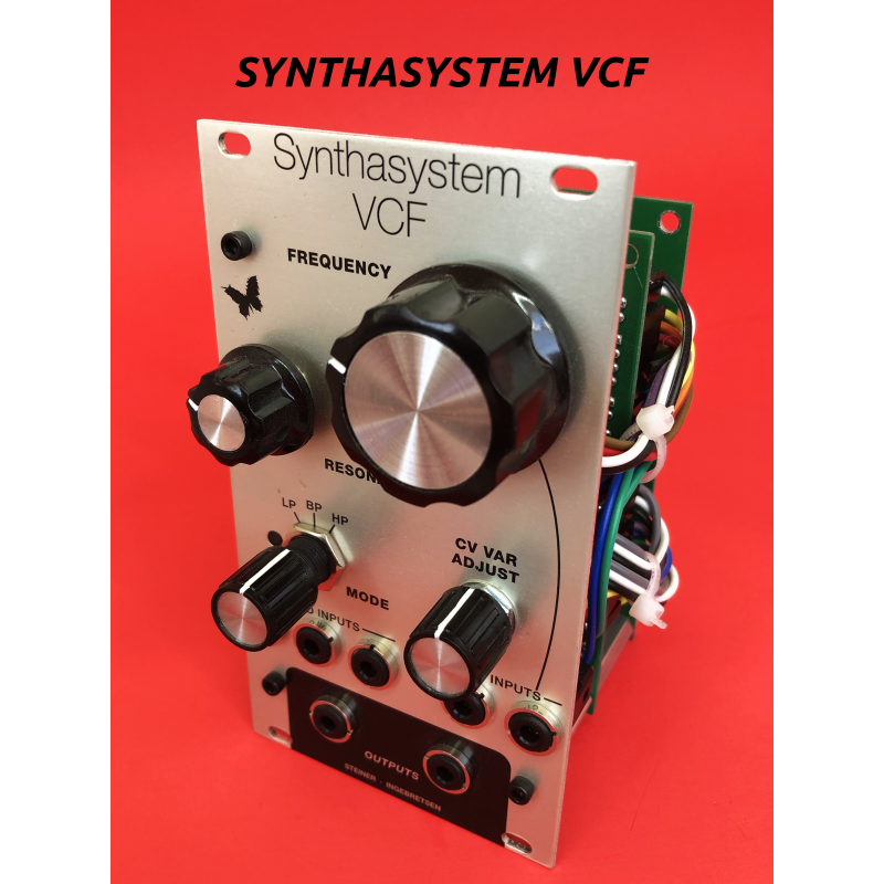
Synthasystem VCF
the classic steiner-parker synthasystem vcf, assembled and calibrated, euro format 14hp
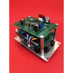
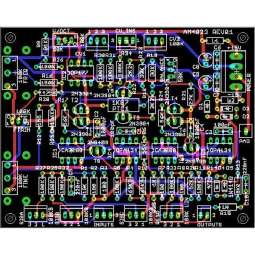
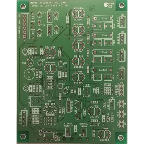
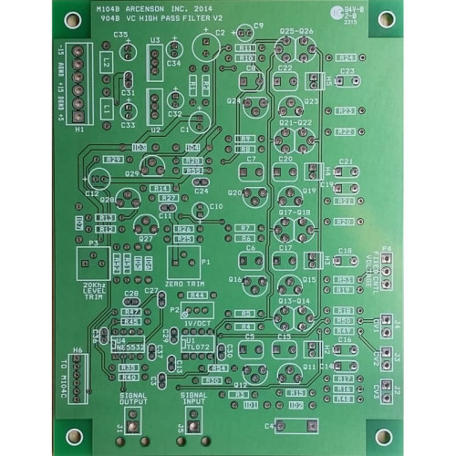
pcbs faithfully reproduced by david ingebretsen from the original schematics
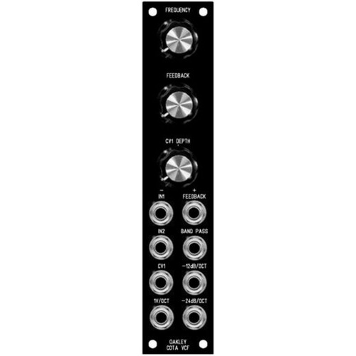
aluminum euro panel by clarke robinson
“This module filters the incoming signals and removes various harmonics to alter the timbre of the signal. The Steiner VCF is as unique as any of the "other" notable filters. In talking to Nyle, he simply said he wanted to design a filter, but didn't want to infringe on any copyrights or someone else's design. This is what he came up with.
This filter has three modes in one filter. A rotary switch selects either High Pass, Band Pass, or Low Pass. Without a full discourse on Filters, the names of these modes are self descriptive. The classic filter is a low pass. However, High Pass and Band pass modes have their own unique effect and place. Every system needs at least three :)
Here is a link to Nyle's paper published in 1974.
From the Synthasystem manual:
The filter is a sound modifier capable of passing certain audio frequencies while attenuating others. All STEINER-PARKER filters are capable of three modes of operation, namely low pass, band pass, and high pass.
The filter also has a variable resonance (Q) knob which will produce a resonant peak at the center frequency. The height of the peak depends on the setting of the resonance knob.
The center frequency of the filter can be controlled by a knob on the front panel and or by control voltages fed into the control voltage inputs.
The filter has three inputs which are automatically mixed in equal proportions before being fed on into the filter. The filter is made to operate in the low pass, band pass, or hi pass mode by turning the mode switch to one of the three positions marked L.P., B.P., or H.P.
The filtered signal comes out of two jacks in parallel marked Sig Out.
The filter can be calibrated by feeding white noise into a signal input, turning the resonance high, plugging keyboard voltage into the VAR jack and adjusting the V.C. Var trimmer until the his pitch shifts one octave when an octave is played on the keyboard.
Use
Inputs/Outputs
This module has two inputs and one output:
1. Signal in - Input a signal to be filtered. Typically an audio signal, but you can remove harmonics from any complex signal. In theory, a sine wave has no harmonics, so it won't do much to a sine except let it through or not.
2. VC In - The cutoff frequency can be controlled by a voltage at these inputs. The primary VC In has a fixed tracking. You can select a different value resistor here if the tracking is not to your liking. The VC Var is summed with the VC In, but has a panel trimmer or potentiometer to set how it tracks. Since these two inputs are summed (along with the Frequency pot), you can create some interesting varying effects
Knobs
This module has 4 knobs:
1. Frequency - This sets an initial cutoff frequency. This setting is summed with the two VC inputs
2. Resonance - This filter incorporates feedback in the design (as do most, (all?) other VC filters I've seen) which adds positive gain to the harmonics at the cutoff frequency. This is one other feature of a VCF which adds to its unique character. The way this original Synthasystem design implements this feedback is different than the many tribute Steiner filters available. Nyle explained to me in this original design, the resonance is less harsh, which he likes better.
3. Mode - This filter is a multi-mode filter and this knob, a three position rotary switch (use the same one as the sequence: Electroswitch C5P0112N-A Mouser number is: 690-C5P0112N-A ) which selects either a High pass, Low Pass, or Band Pass mode. I kept the filter with this mode selector to stay true to the original Synthasystem.
VC Var Adj - There are two VC inputs, (see above). This knob adjusts the tracking for the "VAR" VC input
| Module Parameters | |
| Format | Eurorack |
