WORNG Electronics BuffTest (PCB + Panel)
WORNG Electronics BuffTest (PCB + Panel)
The BuffTest from WORNG Electronics is a dual 1:3 buffered mult with integrated cable tested and manual gate.
It works like a regular buffered mult with a green/red LED to indicate output voltage until the button is pressed, then a positive voltage goes to the top input and a negative one goes to the lower. Joining one of the top outs to the bottom in the module becomes a cable tester, two green lights indicate a good cable, green top and red bottom indicate a broken conductor and green top and off bottom indicates the cable is shorted between signal and ground.
If anyone else has ever suffered the pain of finding one dead lead in a big patch here's some good news: My new design is a buffered mult with a clever little circuit that lets you turn it into a cable tester at the push of a button. It can also be patched as 3x manual gates and, if you can find a use for it, 3x negative gates. Bi-colour LEDs indicate voltage.
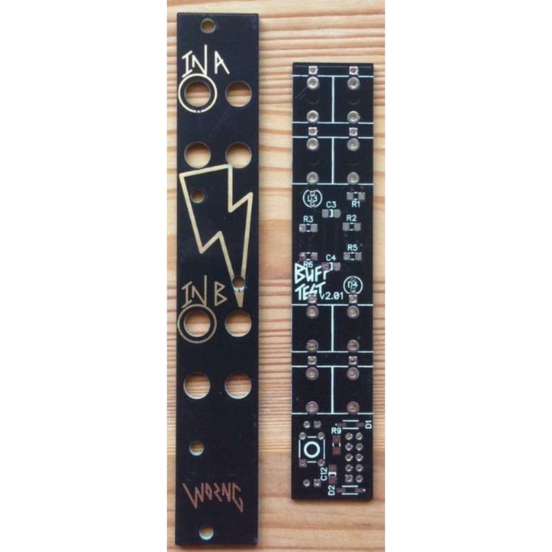
Most passives are 1206 SMT, small enough to save space but big enough to solder by hand with a regular iron. If you haven't soldered SMT before this could be a good first module to try. ICs are SOIC. Jacks are PJ301M-12 (Thonkiconns).
Following feedback from the LRMSMSLR I've put in a footprint for a shrouded power header if you'd like to build his with one. Reverse polarity protection is provided by a pair of diodes.
Front panel is PCB material with black soldermask and ENIG gold lettering. Secondary labelling is printed in the copper under the soldermask so it looks embossed which I think is pretty cool. Also lightning bolts in case you have a Maths v2 and miss the bolts in your case.
Recommendations for patching:
As a buffered multiple: plug your signal/CV to be buffered into IN A or IN B, it will appear buffered on the corresponding outputs. Not there is no normalling from A to B so this can't be used as a 1:6 mult. It will do 1:5 though with a patch lead from an A OUT to IN B.
As a cable tester: IN A must not have anything patched into it. Patch the lead to be tested from any of the A OUTs to IN B and press the TEST button. If the cable is good you'll get two green lights, if the cable has a broken signal conductor you'll get a green light on A and red on B and if the cable is shorted from signal to ground you'll get a green light on A and nothing on B. Note this only tests the signal of the lead, not the ground, but a broken ground connection is very unlikely to be a show stopper in a modular performance, or even effect a patch in the studio.
As a manual gate: with nothing plugged into IN A, pressing the TEST button will give you a ~5V gate on all three A OUTs. As a side effect of the test circuit a negative ~5V signal will also appear on the B OUTs, which could be used a a modulation source, sent to analogue logic etc.


