Barton BMC006 Voltage to Rhythm Converter
Barton BMC006 Voltage to Rhythm Converter
Voltage->Binary Number-> Rhythm.
This module turns voltages into binary numbers in a two different modes series, and parallel.
Both modes utilize analog-to-digital conversion in creating rhythms from beats. In either mode, an
input voltage is sampled and converted to an 8-bit binary number. A clock is then applied and on
each tick of the clock, the output should change.
In series mode, the input voltage is sampled, converted to binary and then the numbers are
cycled through on each clock tick with the 1's represent beats that should be played upon, and 0's
represent beats that should be rested upon. An input voltage of 0v will result in all rests. An input
voltage of 5v will result in all on-beats. All voltages between 0 and 5v will result in a rhythm that
has both rests and on beats. Each output has it's own button and trigger input telling it when to
sample the input voltage.
In parallel mode, the binary number is outputted directly to the outputs, and each clock tick
triggers a resample of the input voltage. So if the input voltag is at 5v when the clock ticks, all
outputs will turn on. If the input is at 0v when the clock ticks, all outputs will turn off.
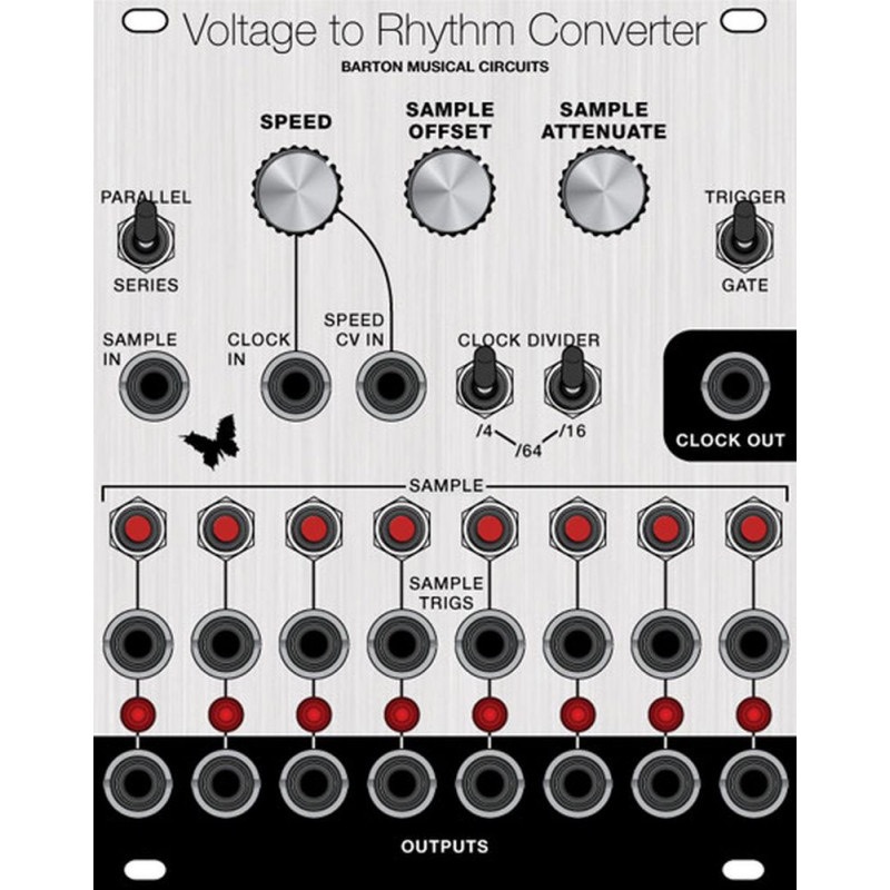
INPUTS
1.Sample input - This is the voltage that will be converted into a binary number. This is a DCcoupled
input that has it's own attenuater and manual offset, so any input voltage can be used.
2.Clock input - When using an external clock signal, input it here. This can accept trigger, gate or
oscillator signals as it's input.
3.Speed cv - When using the internal clock, this is an input for speed control voltage. This voltage
will be summed with the manual speed control.
4.Sample Triggers - There are 8 of these inputs, 1 for each output. Only a gate or trigger signal (a
signal alternating between 0 and 5V) should be used for this input. When a rising gate or trigger is
detected on this input, it will cause the module to resample the input voltage for that output.
OUTPUTS
1.Trigger/Gate outputs - There are 8 of these, one for each channel. These outputs will output either
a gate or trigger corresponding to the current input voltage or sampled voltage depending on the
mode of operation you are in. Each has an LED corresponding with it's output.
2.Clock output - This outputs a trigger on each new clock. It is active whether using the internal or
external clock.
CONTROLS
1.Sample Attenuator and offsetter - These two control knobs condition the external sample voltage.
When no external sample voltage is used, the offsetter can be used to manually select the sample
voltage. To get the full range of inputs from an input in the 0 to 5v range, like a seqeuncer, turn the
offset knob fully counter clockwise and the attenuater fully clockwise. To get the full range of
inputs from an input in the -5V to +5v range, like an LFO, turn both knobs to be halfway up.
2.Speed - When using the internal clock, this controls it's speed.
3.Sample buttons - There are 8 of these, one for each output. Pushing one of these while in series
mode will cause that output to resample the input voltage.
4.Parallel/Series switch - This switches between series and parallel modes of operation.
5.Trigger/Gate switch - This switch determines whether outputs will be triggers or gates. Gates
remain on until an off-beat is presented, triggers turn on for 5ms at the start of each on-beat.
6.Divide switches - These switches cause division on the clock signal. One divides by 4 and the
other divides by 16. When both are used, this causes a division of 64.
These kits and assembled modules are offered on demand, click the link to learn more.
| Kit Parameters | |
| Build Difficulty | moderate |
| Parts Count | 119 |
| SMT parts | none |
| Module Parameters | |
| Format | Eurorack |
| Panel Size | 20HP |
