Synthasystem Voltage Sequencer
Synthasystem Voltage Sequencer
this is a very special module, a modern re-release of the classic steiner synthasystem sequencer.
originally designed by nyle steiner with new pcbs by david ingebretsen and 56hp euro panel design by clarke robinson.
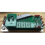
the pcb set includes 3 pcbs-- logic pcb, output pcb and power pcb.
more information and documentation is here: synthasystem sequencer
from david ingebretsen's site:
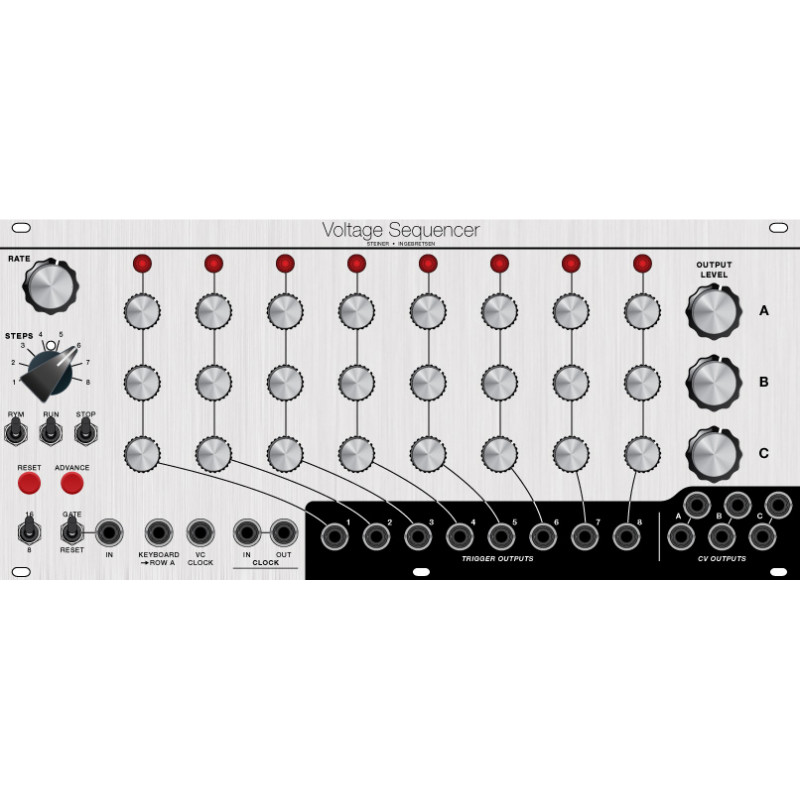
"This module produces a series of DC voltages which can repeat. These voltages can be set by potentiometers arranged in 3 rows of 8 each. There are several controls which affect how the sequence plays and interacts with the user. This sequencer is unique in that it is as much instrument as a way to memorialize a particular 1 to 16 step musical progression. The various controls allow for real time user interaction as much as setting it, and letting it go.
This module has 4 input jacks and 12 output jacks.
Inputs:
- Gate/Reset – This is actually 2 inputs depending on the state of the “Gate/Reset” switch. The normal mode is “Reset”. A trigger on this input in “Reset” mode will cause the sequencer to start over at step one. In the “Gate” mode, the sequencer will only operate when there is an active “Gate” signal on the input. EG: with a keyboard “Gate” signal on this jack, the sequencer will only play with a key is down (the “Stop” switch affects how the sequence plays. See below).
- Keyboard Sum -> A – This input is intended to accept a DC voltage which is summed with the output of row “A” like the voltage output from a keyboard. This is useful when you want to keep a sequence tuned to a specific relative musical interval as you play the keyboard.
- VC Clock – This input accepts a voltage which then controls the frequency of the internal clock.
- Clock In-Out – This is an input and an output (see below under outputs). Since this module uses S-Triggers, you can input an S-Trigger clock signal (such as created from the Peak Selector, Voltage Controlled Trigger Generator, etc.) which is combined with the internal S-Trigger clock if in the run position. If the “Run” switch is off, the external clock controls the timing. If you want to sync or trigger another module, (Envelope Generator?) to/from the Sequencer, this jack can be used as an output. There are two jacks so that if you wire it for Voltage Triggers, you can wire one as an input and one as an output. You lose some of the advantage of S-Triggers by moving to Voltage Triggers, but it becomes an invisible conversion and makes the Sequencer play nicely with V-Triggers.
Outputs:
- Trigger Outputs 1-8 – These jacks produce an S-Trigger on each corresponding step. These are useful to trigger different events at different steps in the sequence.
- Out A, B, and C – These are the main outputs from the Sequencer. The DC voltage at each of these jacks is determined by the setting of the knobs on each corresponding row and step. An LED on top of each column will indicate which step is active. Row A and B can be combined in series so you can have a 16 step maximum sequence. More on this under “Switches”.
- So far, 11 outputs. The 12th output is the Clock In-Out which was already discussed.
| Kit Parameters | |
| Build Difficulty | Advanced |
| Parts Count | 484 |
| Module Parameters | |
| Format | Eurorack |
| Panel Size | 56HP |
